 HELIX delta-Q2 Pipe Network Analysis Overview
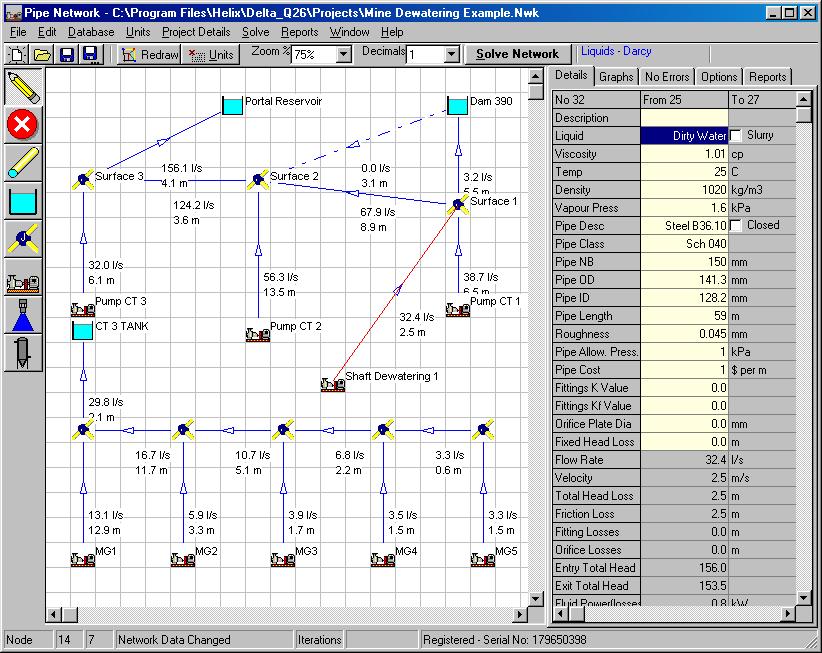
Delta-Q2 is a powerful tool for engineers and equipment suppliers to quickly and easily design and optimise pipe networks for compressible and incompressible fluids. You can produce economically and technically sound pipe system designs in a very short time.
You can calculate friction losses and pressure drop in pipes and fittings for Liquids, Slurries and Gases and Model complex process flow pipe networks and solve for unknown flow rates and node pressures at the press of a button. Retrieve data from user accessible databases for Liquids, Slurries, Gasses, Pumps, Pipes and Fittings or add your own data.
Drag and Drop components into your Network 
Now delta-Q includes a CAD DXF file generator for exporting the network diagram to CAD. This means you can draw the network in Delta-Q, solve it and then export it to CAD for plotting as large format drawing.
See the Sample CAD DXF file generated by Delta-Q DeltaQ Drawing PDF
Design and analyse complex pipe networks for :
- Water Supply Schemes
- Irrigation Systems
- Fire Protection Systems
- Mining Process Plants
- Tailings Slurry Disposal
- Mine Dewatering
- Dredging Operations
- Chemical Process Plants
- Hospital Gas Reticulation
- Steam Process Systems
- Gas Distribution & Storage
- Oxygenation Plants
- Oil & Gas Installations
- Air-conditioning & Ventilation
- Compressed Air
- Dust Extraction
- Many more..
Features of Delta-Q2
- Design and Solve Complex Pipe System Networks.
- Solves for any number of pipes, nodes and pumps. Uses matrix algebra combined with the Newton-Raphson method for quick, accurate convergence.
- Drag and Drop Network components onto the screen for quick and easy network creation.
- Add individual fittings to pipes using the fitting database or enter an estimate of the total K value.
- Calculate Fitting Losses using the standard K value method or the Kf method which compensates for fluid viscosity and turbulence.
- Comprehensive Databases for Pipes, Liquids, Slurries, Gasses and Pumps.
- Setup individual Fluids and properties in each pipe - Model real world process flows with different fluids in the same network.
- Model what if scenarios - close off certain pipes and view the effects on the network.
- Display the Network Calculation Results such as Pipe Flows, Velocity, Head Loss, Node Pressure and many others on the Network Diagram.
- Network Reports Display and Print the Network Pipe and Node Data and Calculation Results in compact Tabular Form.
- Export the Results to Spreadsheets like MS Excel®
- Click on a Pipe to View the System Curve with the Network Duty Point shown.
- Perform Complex Orifice Plate Calculations automatically merely by adding an Orifice to a Pipe.
 |
Add an Orifice plate to any pipe, or specify a fixed pressure drop. |
Include Networks with unknown pressure nodes and unknown flow nodes or any combination of the two.
Model networks containing any number of pumps, reservoirs and spray nozzles and other components.
Build a Model to simulate almost any Process Flow condition including pipes, fittings, valves, pumps, orifice plates, vessels, sprinklers, nozzles, columns, flow and pressure control valves.
Model any number of pipes, junctions, pumps, vessels, sprinklers, nozzles, tanks, intakes, and outlets as you like in one network.
Add individual fittings to each pipe or enter a global K value or Kf value for a quick estimate of fitting losses.
You can have different fluids in the same network. For example, you may have a concentrated slurry in one pipe flowing into a junction with a water pipe (or pipes) and dilute slurry flowing through the network from that point onwards.
Pipe capital vs. operating costs are calculated to assist you to make decisions on the most economical pipe size for an application.
Use any Engineering units you require - it is easy to add your own units, or select Metric, SI or English units supplied with the program.
The program is supplied with Sample files and on-line Help to get you started quickly and easily.
deltaQ2 Sample Reports and Drawings
You can view sample reports and drawings by clinking the links below:You can download a sample drawing of a Nickel Plant Fire Water Pipe Network: Fire Water Network Drawing - pdf file
Download the Model Data Reports for the above Fire water system: Fire Water Network Data Report - pdf file
You can download a Delta-Q2 brochure: Delta-Q2 brochure - pdf file