HELIX delta-T6 Dynamic Analysis 
A version of the program which has full flexible belt Dynamic Analysis capabilities has been available in Helix delta-T since 2003. This version calculates the transient belt Tensions and Velocities during starting and stopping of a conveyor. It can model the conveyor belt transient behaviour during Starting Fully Loaded, Starting Empty, Stopping Fully Loaded and Stopping Empty.
This new version of the program which has full Dynamic Analysis capabilities is essential for designing high powered conveyors and long overland conveyors. The Dynamic analysis version includes the Standard and Professional versions of the software. If the installed power on a conveyor is more about 800kW then Dynamic Analysis of the conveyor starting and especially stopping is recommended.
The program allows the user to input any number of Drives or Brakes and allows for input of Drive Torque / Speed curves, Delay times, Braking Torques, Flywheels and inertia effects. After the Dynamic Calculations have been performed, the user can view and Print two dimensional and surface plot three dimensional graphs for Belt Tensions, Belt Velocities, Strain rates and Takeup movement versus time step for all points along the conveyor.
Video of Conveyor Belt Contracting and Running Backwards at Tail
Video of Conveyor Stopping Fully loaded - note reverse running after belt reaches zero velocity
Helix Belt Velocity of Conveyor Belt Contracting and Running Backwards at Tail
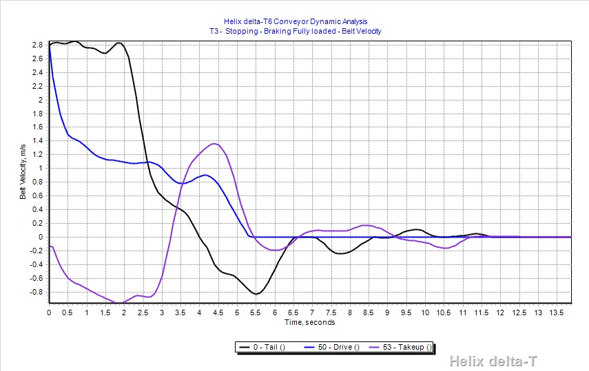
The graph above shows the results of the stopping full dynamic analysis calculation; this is a graph of the Belt Velocities and you can see the program shows the Tail pulley (black line) running on at belt speed for 2 seconds, then decelerating and after the initial stop it has a negative velocity from 4.0 seconds to 6.5 seconds - this is the belt running backwards.
It has a final forward velocity for a short time shown in the graph and also in the video. This conveyor is almost flat so the run-back is not due to gravity but due to the very flexible Fabric reinforced belt contracting and so running backwards at the Tail Pulley.
Helix Dynamic Analysis Calculation Method
The Dynamic calculation process uses sophisticated Variable Step Runge Kutta method integrators for solving the complex differential equations. All the numerical analysis is compiled into the program and it does not require any other software to perform the calculations or display graphs etc. It also allows flexible, easy to use boundary condition specification by the user.
Helix delta-T uses a Finite Element model of the conveyor to perform the dynamic analysis. The conveyor is broken up into segments, and for each segment, we use a Kelvin solid model, which is a spring in parallel with a viscoelastic element, as shown below:
Kelvin Solid Model
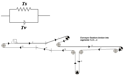
Conveyor Model Diagram
The conveyor model created and captured in the normal delta-T program is automatically broken up into segments in the Dynamic Calculation process. The program already knows the geometry of each section of conveyor, as well as the idler spacing, rotating masses, resistances, inertias, drive power and location, takeup mass and the equivalent mass of each element in the conveyor. The Dynamic calculation breaks the standard conveyor sections into smaller segments. The designer can specify the maximum segment length to be used.
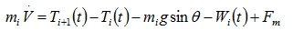
Delta-T uses the Finite Element method of dynamic analysis Once the conveyor is segmented, the moving mass, length etc. of each segment is known. The Tension force acting on segment i at time t is given by the sum of the spring and viscoelastic Tension forces, Ts and Tv respectively. At each time step of say 0.1 seconds, the rate of change of velocity, combined with the strain on each conveyor segment is calculated. The peripheral force at the drive pulleys is the motivating force. The main conveyor resistances, represented by the Coulomb friction factor f, which is a function of instantaneous belt tension and belt sag at the segment under consideration, are taken into account. All idler roller rotating masses and pulley, drive and brake inertias are included in the acceleration and tension calculations. The Drive Torque or Velocity is input graphically, and the resulting Belt Tensions, strains and belt Velocities are output for each time step and for each point along the conveyor. These values are presented graphically for ease of interpretation.
Dynamic Analysis Graphs
| Dynamic Analysis Graphs | |||
|---|---|---|---|
| Graph Description | 2D Graph | 3D Graph | Remarks |
| Belt Velocity at each pulley / point in conveyor | User can plot all points or any point | ||
| Belt Tensions at each pulley / point in conveyor | " | ||
| Take-up Travel at each pulley / point in conveyor | Only Take-up plotted | ||
| Pulley Torque at each pulley / point in conveyor | Drive and Brake Pulleys | ||
Dynamic Analysis Features
The Dynamic Calculations are easy use to use and Engineers who have static conveyor design experience can perform these complex dynamic simulations using this very powerful software.
- Easily model the belt transient tensions and velocities during Starting and Stopping of conveyors.
- Add Torque Control or Speed Control on drive acceleration.
- Add Delay times for multiple drives for Dynamic Tuning.
- Add Flywheels to pulleys to optimise starting and stopping.
- Add Brakes to pulleys as required.
- Calculate Dynamic Runback forces and size holdbacks for dynamic loads.
- View the movement of the Takeup pulley during Starting and Stopping.
- Predict the maximum Transient Belt Tensions at any point along the conveyor as well as the timing of these transients.
- Compare the Dynamic Calculations results with the rigid body static calculations in the delta-T5.
- Predict the magnitude of transient loads on conveyor structures.
- Calculate the torque loadings on gearboxes, holbacks and couplings during starting and stopping. Eliminate conditions which may cause costly equipment failures.
- Perform Dynamic Tuning by changing the start delay times on different drives.
- Helix delta-T allows the designer to control the starting of a conveyor by means of:
-
Starting - Stopping Control
- Torque Speed Control - Starting - e.g DOL, Wound Rotor, Fluid Coupling etc.
- Speed Time Control - Starting e.g VVVF Variable Speed Drives, DC Motors
- Constant Torque Brake - Stopping e.g Disc Brake
- Speed Time Curve Control - Stopping e.g VVVF Controlled stop (ramp down)
- The Take-up can be locked on stopping to use belt stretch tension for sag control
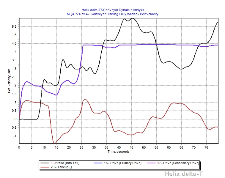
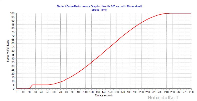
Sample of Belt Velocity Graph for conveyor starting
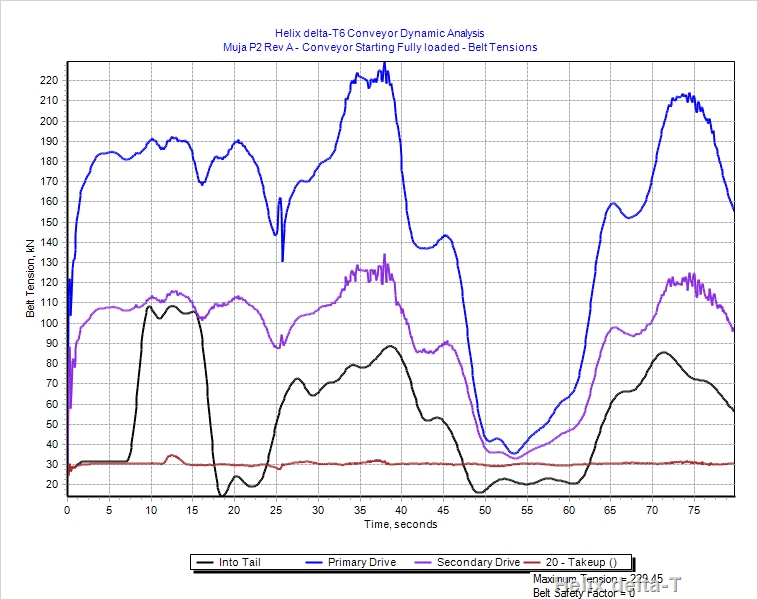
Sample Belt Tension Graphs for conveyor starting full
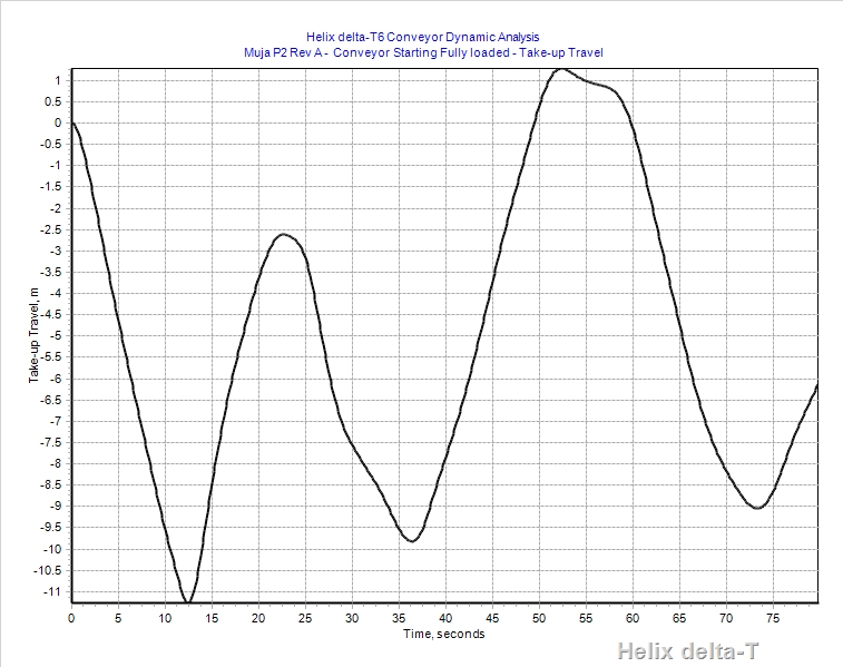
Takeup Travel Graph
Example of Dynamic Analysis - conveyor stopping loaded
Belt Velocities
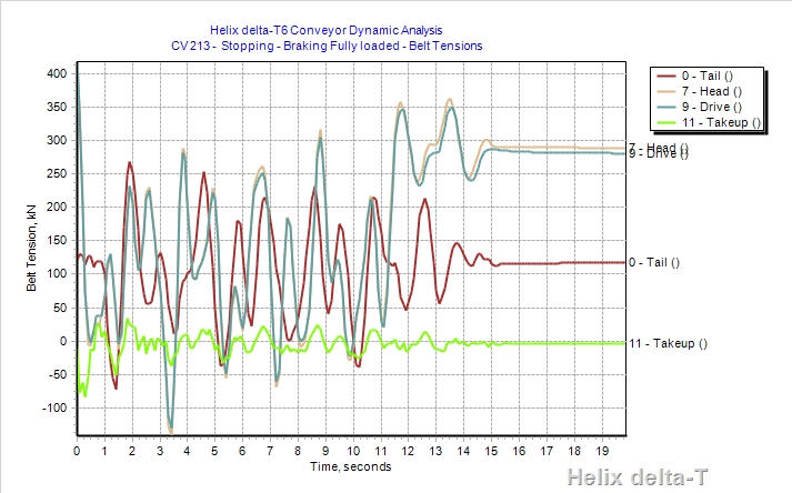
Belt Tensions
 Note Tension rise as conveyor comes to rest and holdback locks up at 11.5 second mark.
Sample of VVVF Variable Speed Drive Starting Ramp using built in spline curve generator
You can download a Sample of a Conveyor Dynamic Analysis report for a 6.7kM long overland conveyor Sample Dynamic Analysis report - zip file. Save the file to disk and then unzip it and view the Word doc with reports and graphs generated from Helix delta-T