HELIX delta-T6 - Belt Turnover Calculations 
Belt Turnovers are sometimes used on conveyors to flip the belt over through an angle of 180 degrees. This is often used in order to keep the belt cover which is in contact with the idlers on the carry side of the belt also in contact with the idlers on the return side of the belt. This is an advantage when the belt has a Low Resistance Rubber cover on the bottom cover and it is then turned over after the discharge and drive pulleys so that the low resistance rubber is utilised on the return run as well as the carry run. The belt is then turned back over at the tail end of the conveyor. Another advantage of the turnover is that material which may be stuck to the carry side of the belt will be shed by gravity, idler roller contact and vibrations on the return run.
Twisting the belt through 180 degrees causes the belt edge to be elongated and this increases the edge tension in the belt with a corresponding reduction in center tension, similar to the belt transition from troughed to flat at a discharge pulley. A calculation of the magnitude of this tension rise as well as the belt sag between supports is required in order to ensure the belt is not overstressed. Also, the belt should not be subjected to compressive forces (negative tensions) at the centre. Twisting the belt 180 degrees over too short a length will result in excessive edge tension and or compressive centre tensions.

Use the main form main menu Calcs, Calculate Belt Turnover to open the calculation form.
Use the main form main menu Calcs, Calculate Belt Turnover to open the calculation form.
Enter the Belt Tension at the turnover, belt width, belt mass, belt strength and allowable run tension, belt modulus and if it is a steel belt enter the cord diameter. If the belt is a fabric belt the cord diameter can be entered as 1mm.
If the belt has quarter turn support rollers (angled at 45 degrees) to support the belt in the turnover, check the Turnover Has Quarter Support Roller checkbox to ON, leave it off of there are no intermediate support rollers. This check box does not refer to a set of vertical support rollers at the midpoint. The Quarter turn support rollers help to reduce the belt sag in the turnover.
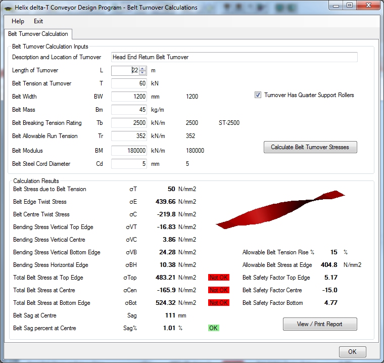
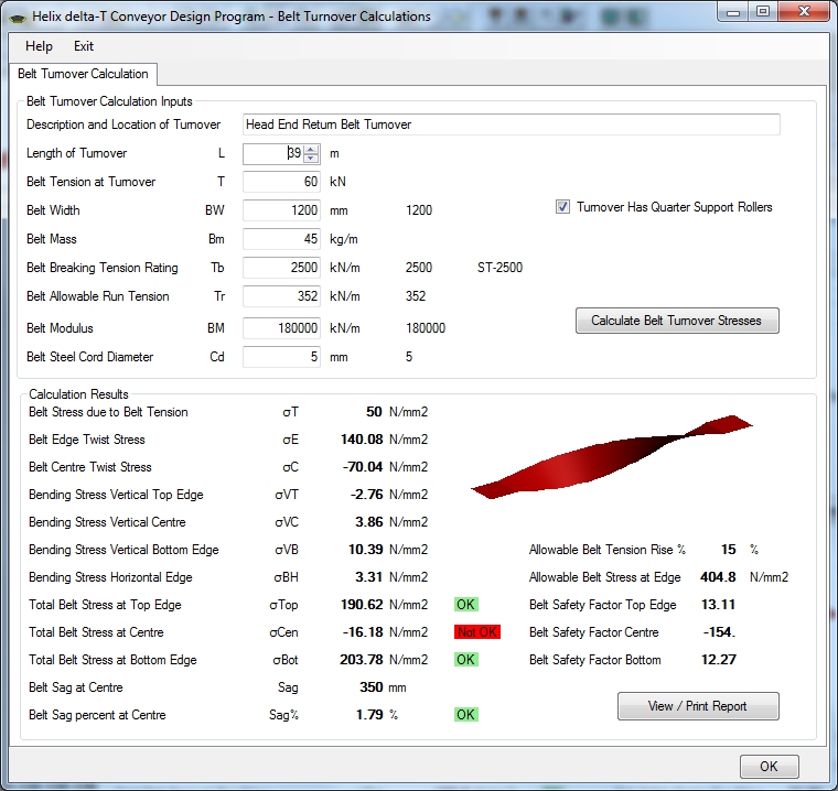
Now use the spin button on the Length of Turnover input box to find the shortest turnover length which does not have a negative centre tensions. In the example above the 22m long turnover has excessive edge tension and negative centre tension, flagged by the Red Not OK warning labels. Increasing the turnover length to 39m, as shown below, reduces the edge tension to acceptable values but the centre tension is still negative.
Increasing the turnover length to 45m, as shown below, reduces the edge tension to acceptable values and increases the centre tension to positive values.
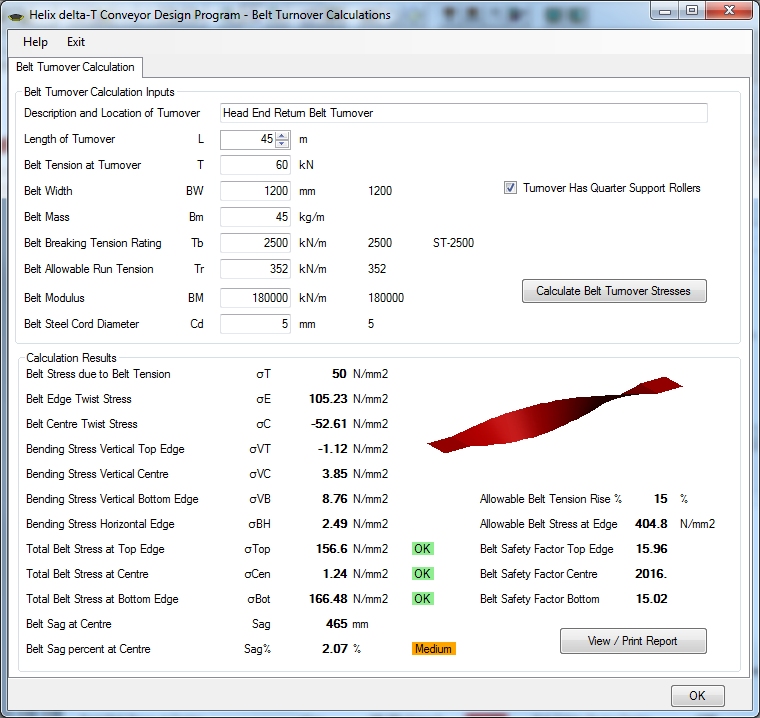
The belt sag has increased to 465mm and this is just over 2% of the length of the turnover between quarter support rolls.
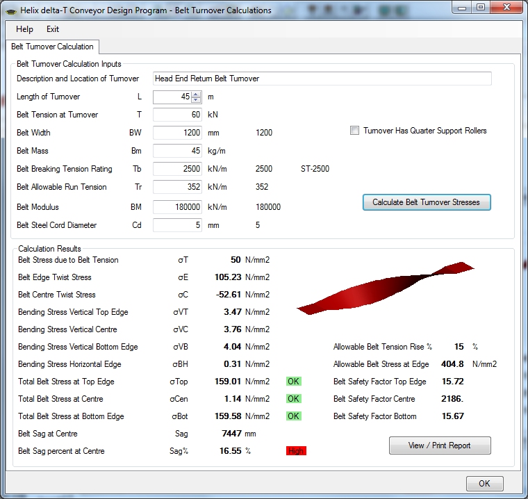
The case without quarter support rolls has a very large sag of 7447mm and is flagged as High sag because the sag exceeds 5% of span. A flag of Medium is shown for sag between 2% to 5% but there is no specified limit, the amount of acceptable sag is up to the designer.
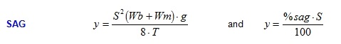
The belt edge tension and centre tension stresses are calculated from the elongation of the belt due to twisting. The belt sag is calculated as for a catenary using only the first term of the series.
Bending stresses in the steel cords are generally low and are calculated from the curvature in the cables due to belt sag.
You should use the minimum turnover length which yields acceptable edge tension and positive centre tension and depending on the belt tension in the turnover, quarter support rolls will probably be required in order to limit the belt sag to acceptable levels.
Repeat the calculations for all belt tensions which will be experienced in the Turnover. You can print out the calculation report by using the View / Print Report button